

How does a generator engine works?
We will go really in-depth for this one. There are several terms you need to know to have a full understanding of the way an engine operates. Knowing these terms discussed in this blog allows better understanding of your generator’s engine operation. The following table includes terminology used when collaborating in the operation of an engine. Always refer to manufacturing manuals for all other guidance.
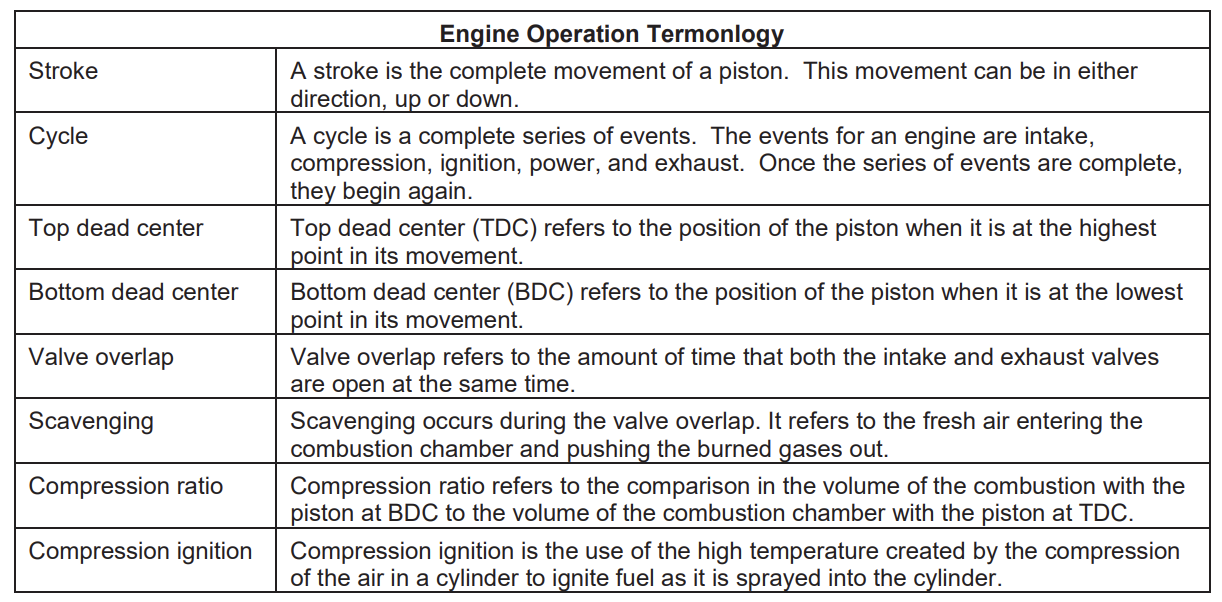
These terms are key to understand the basis behind the theory that you are about to read.
All internal combustion engines must have air, fuel, and ignition. Engines use two basic designs—the two-stroke and the four-stroke. This refers to the number of strokes it takes to complete a cycle. Regardless of the type of engine, the sequence of events remains the same.
The events discussed in this blog are intake of fresh air, compression of the fresh air, ignition, burning of the air fuel mixture to create power, and the exhausting of the burned gases.
Two-stroke DIESEL engines
As the name of the two-stroke engine implies, a complete cycle of events occurs in two strokes of the piston. The two-stroke engine typically has intake ports located in the bottom of the cylinder wall and exhaust valves in the cylinder head. The intake ports receive air from a cavity called an air box. The engine uses an external blower to pressurize the air in the air box. This allows the air to rush into the cylinder when the port is open. In the normal sequence of events, the piston is located at BDC and is beginning to move up. The pressurized air rushes into the cylinder. The exhaust valve is also open at this time. Shortly before the piston covers the port, the exhaust valve closes trapping the air in the cylinder. The pressurized air continues to flow into the cylinder until the piston moves up enough to completely cover the port; this is the intake event. Once the port is closed, the piston continues to move up compressing the air in the cylinder. This continues until just before the piston reaches TDC. This compression of the air causes the temperature to rise to over 1,000°F; this is the compression event. Fuel gets injected into the cylinder just before TDC. Since the combustion chamber has a high temperature created by the compression of the air, the atomized fuel immediately ignites. The combustion of the fuel expands to fill the space between the cylinder head and piston at the same time the piston reaches TDC; this is the ignition event. The burning fuel continues to expand, pushing the piston down. This push continues until the exhaust valve opens; this is the power event.

Two-stroke principle
Following the power event, the exhaust valve opens allowing the pressurized gases to begin flowing out of the cylinder. The piston then uncovers the intake port and the fresh air begins to flow into the cylinder, pushing the exhaust gases out. This continues as the piston reaches BDC and begins its upward movement. Just before the piston reaches the top of the port, the exhaust valve closes; this is the exhaust event. Two-stroke engines depend on scavenging to operate. The inrush of fresh air is the only means of removing all of the burned gasses from the cylinder. The use of a blower creates this movement of air. Two-stroke engines will not operate without a blower because there would be nothing to remove the burned gasses from the cylinder.
Four-stroke DIESEL engines
The four-stroke engine requires four strokes of the piston to complete one cycle of operation. This is different than the operation of the two-stroke that you have just read about. The four-stroke engine also has a few components that are different than the two-stroke. The four-stroke engine typically uses an intake manifold and ports in the head to direct fresh air into the cylinder. The airflow is controlled by an in intake valve. This means the four-stroke engine has both intake and exhaust valves. In the normal sequence of events, the piston is located at TDC and is moving down. The intake and exhaust valves are both open. As the piston starts its downward movement, the exhaust valve closes leaving only the intake valve open. The downward movement of the piston creates a vacuum that draws fresh air into the cylinder. This continues until the piston reaches BDC; this is the intake event. Once the piston reaches BDC, it begins moving upward. The intake valve then closes, sealing the cylinder. The piston continues to move upward, compressing the air. This is the compression event. Fuel is injected into the cylinder just before TDC. The high temperature created by the compression of the air and the atomized fuel causes ignition. The combustion of the fuel expands to fill the space between the cylinder head and piston at the same time the piston reaches TDC. This is the ignition event. The expansion of the burning gasses continues to push the piston downward. This energy transfers to the crankshaft through the connecting rod. This continues until the exhaust valve opens just before the piston reaches BDC; this is the power event. Once the exhaust valve opens, the burned gasses begin to flow out of the cylinder. The piston reaches BDC and begins its upward movement. This movement forces the exhaust gases out of the cylinder. Just before TDC, the intake valve opens and scavenging takes place as the piston reaches TDC; this is the exhaust event. Four-stroke engines do not require a blower to operate because of the vacuum created by the movement of the piston. This vacuum allows the engine to operate at normal atmospheric pressure. This we refer to as a naturally aspirated engine.

Four-stroke principle
Four-stroke GASOLINE engines
The gasoline four-stroke engine operates on the same principle as the diesel four-stroke engine. The movements of the piston and valves are the same. Although there are a few differences between the two types which are found mainly in the fuel and ignition systems. This blog discussed the events that occur that completes the engine cycle.
Engine components and operations
The fuel system consists of a carburetor or injectors. The carburetor mixes the intake air and gasoline before they enter the cylinder. Therefore, the cylinder takes in an air and fuel mixture. In some, gasoline engines injectors are used and the fuel is injected into the intake ports or manifold. Additionally many new engines use direct injection like as diesel but the fuel ignited using a spark plug.
The ignition system is also different from diesel. The gasoline engine uses an electrical system where the diesel uses compression ignition. The gasoline engine’s ignition system provides an electrical spark at the proper time to ignite the air/fuel mixture.
Ignition system
The ignition system provides an electrical spark in the combustion chamber at the proper time to ignite the air/fuel mixture. Using either a battery or a magneto system accomplishes this. The battery system is by far the more common today, though you still find magneto systems on some equipment. Regardless of the system the engine uses, it must deliver voltage to the spark plug that is high enough to jump the gap and create a spark at the proper time for ignition purposes.
Battery ignition system
This system uses several different components to create the electrical spark in the combustion chamber. These components include the battery, ignition switch, ignition coil, breaker points, condenser, distributor, high-tension wire, and spark plug. The ignition coil contains two coils, the primary and secondary windings. When the ignition switch is turned on; current flows through the breaker points and ignition coil. This causes a magnetic field to build up around the coil. When the breaker points open, current flow abruptly stops and the magnetic field of the coil collapses. This collapse of the magnetic field causes a massive buildup of up to 250 volts in the primary and secondary coils. The primary coil discharges back toward the condenser, which absorbs the voltage. Without the condenser, the voltage would arc across the breaker points causing them to burn. The condenser holds the voltage momentarily, and then discharges it. The breaker points close as this discharge from the condenser occurs providing a path of current flow back to the battery.
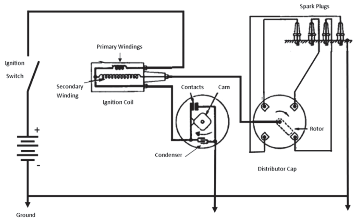
Battery ignition system schematic.
The secondary coil is much larger than the primary coil, often containing about 100 times as many turns. This causes the secondary coil to build up much more voltage, up to about 25,000 volts than the primary coil. This voltage discharges through the high-tension wire to the distributor. The distributor connects the coil to the cylinder that is about to fire. The voltage continues through another high-tension wire to the spark plug. The spark plug mounts in the cylinder head with the electrode extending into the combustion chamber. The high voltage created by the secondary winding causes an arc across the gap in the electrode. This arc ignites the air/fuel mixture in the cylinder. The amount of voltage required to jump a gap on an electrode of a spark plug is about 6,000 to 20,000 volts. The exact amount varies based several variables including the amount of compression, type of spark plug, shape and condition of the electrodes, and spark plug gap.
Electronic ignition system
Many gasoline engines use an electronic ignition system. These systems are a type of battery ignition system since they use a battery for operating voltage. There are different types of electronic systems. One type of electronic system uses a distributor, which has several components that ensure correct spark timing. Hidden under the distributor cap is an ignition signal sensor, which senses a spot on the cam and sends a signal to the ignition module. The ignition module then closes the circuit to ground coming from the ignition coil. When this happens, the coil sends voltage to the distributor cap. Once the voltage gets to the cap, the voltage is transferred to the rotor, which is timed to the correct position on the cap in order to send the voltage to the appropriate cylinder’s spark plug. In other words, this electronic ignition replaces a mechanical set of points with a solid-state component to time ignition from the coil. These systems tend to need less maintenance due to the lack of mechanical points, but they still require periodic maintenance that usually involves replacing the cap and rotor.
Another type of electronic ignition is called distributor-less. This system will have either a coil pack, which will send voltage to the correct cylinder via a spark plug wire, or will have a coil for each individual cylinder that receives a signal from the engine control module. In this configuration, the coil is directly attached to the spark plug. Both of these systems require very little maintenance because they do not contain any moving parts and the spark timing is controlled electronically to deliver the spark at the most optimal time no matter the operating conditions.
Magneto ignition system
The magneto ignition system is similar to the battery ignition system. The components that make up the magneto ignition system are a permanent magnet, ignition coil, breaker points, condenser, high-tension wires, and spark plug. The ignition coil contains two coils, a primary and a secondary. The primary coil typically has about 150 turns of fairly heavy copper. The secondary coil often has about 20,000 turns of fine copper wire. The ignition coil also has an odd shaped core, which is designed to efficiently direct the magnetic lines of force around the coils. This design enables the magneto to produce a voltage that is sufficient to jump the spark plug gap.
The basic operation of the magneto ignition system is the same as the battery system except for the power source. The permanent magnet provides the power. As it passes the core of the coil, lines of force flow to create a magnetic field in the primary coil. This produces current from the coil, through the breaker points, to ground. As the magnet reaches the secondary coil, the breaker points open. This creates a sudden collapse of the magnetic field. The condenser absorbs the current of the primary coil to prevent the burning of the breaker points. This collapse of the magnetic field induces a voltage on the secondary coil. This creates high voltage that moves to the spark plug to create a spark.
Fuel system
The gasoline fuel system supplies fuel to the engine for combustion. The fuel vaporizes and mixes with air before it reaches the cylinder. The normal mixture is 15 parts of air to 1 part of fuel. This ratio varies from start up to acceleration. The main components of a gasoline fuel system are the fuel filter, fuel pump, and carburetor.
Fuel filter
The fuel filter is a unit that removes dirt and foreign particles from the gasoline. Without the filter, these particles would get into other components of the fuel system and clog fuel passages. Many of these filters are sediment-bowls that use a bowl and screen to filter the fuel. In this type of filter, the fuel enters the bowl and passes upward through the filter screen before flowing through the outlet. Any water or solid matter caught by the screen falls to the bottom of the bowl, where you can remove it. Other fuel filters use metal-disc, porous-clay, absorbent-cloth, or paper filter elements. All filters, regardless of their design, remove particles from the fuel.
Fuel pump
The fuel pump is a mechanically or electrically operated device that moves fuel from one point to another. The engine camshaft usually drives the mechanical pump, while batteries usually drive the electronic pumps. The fuel pump transfers gasoline from the fuel tank, through the fuel lines, to the carburetor. The pump also keeps the gasoline under a constant pressure.
Carburetor
The carburetor mixes the liquid gasoline with air that is moving on its way to the engine cylinders. To do this, the carburetor uses a venturi. The venturi is a restriction in a passage that causes air to move faster. This increase in velocity causes a decrease in pressure. The greatest speed occurs at the point where the restriction is the greatest. As the restriction reduces, the speed of the air slows.
The fuel nozzle extends into the passage at the point in the venturi where pressure is at its lowest level, as shown in the figure below. The decrease in pressure in the passage creates a vacuum, which draws partially vaporized fuel into the passage. The speed of the air in the venturi further vaporizes the fuel. The fuel often does not completely vaporize until it reaches the cylinder and is compressed.

Venturi principle.
The carburetor varies the proportions (ratio) of gasoline and air, changing the mixture. A lean mixture is when less fuel (than is required for the given about of air) is present and if a mixture is rich it contains more fuel. The position of the throttle valve controls the amount of air-fuel mixture that enters the cylinders during the intake strokes. Though there are many variations and designs of carburetors, they all perform the same function.
Some of the basic components of the carburetor include: the bowl, float, choke system, venturi, nozzle, throttle valve, load adjustment, and idling circuit. The following list defines each component.
Bowl–The bowl is a small storage area for gasoline in the carburetor.
Float–The float is a small sealed vessel normally made of brass or plastic. The float maintains a constant level of fuel in the bowl. The float rises and falls with the fuel level. As the float lowers with the level of fuel, it unseats a needle valve, which allows fuel to enter the bowl. As the float rises, it seats the needle, thus shutting off the fuel.
Choke–The choke is a round disc, mounted on a shaft that is located at the intake end of the carburetor. When the choke is closed, it provides a rich mixture of air/fuel that is necessary for cold starting.As the engine warms, less choke is required.
Venturi–The venturi is a restriction in the air passage.It causes an increased air velocity as the air reaches the venturi. This change in air speed causes a pressure change. The pressure decreases, creating a vacuum.
Nozzle–The nozzle is a tube that connects the bowl to the air passage.It transfers the fuel from the bowl to the venturi. This is sometimes referred to as a jet.
Throttle valve–The throttle valve is a round disc mounted on a shaft and is located beyond the main fuel nozzle. The throttle valve regulates the amount of air/fuel mixture entering the cylinders by restricting the passage.
Load adjustment–You do load adjustment by use of a fixed jet or orifice, which allows a preset amount of fuel flow for maximum power and economy. Carburetors equipped with a fixed jet are non-adjustable.
Idling circuit–The idling circuit supplies just enough air/fuel mixture to keep the engine running when the engine is idling. The throttle valve closes during idle.
Fuel injection
Automobiles and industrial engines have used fuel injections systems for several years. These systems replace the carburetor with fuel injectors. These injectors fall into two categories, port and throttle body. Port injectors inject fuel directly into the intake manifold or cylinder head just before the intake valve. There is an injector for each cylinder the engine has. The throttle body injectors use a device similar to a carburetor with an injector built into it. Either way, the injectors are basically electronic metering valves. This allows the injectors to provide precisely controlled amounts of fuel to the engine based on speed and load.
Older systems used differences in pressures created by an engine driven fuel pump to vary the amount of fuel supplied to the engine. Newer systems use electronically controlled needle valves to adjust the amount of fuel sprayed into the engine. These systems use a solenoid to control the movement of a needle valve. The position of the needle valve controls the amount of fuel supplied to the engine. Fuel injection systems are much more efficient and provide quicker response to speed and load changes.
Do they require maintenance?
Generators require careful routine maintenance at regular intervals. This depends on the manufacturer, but the most important item to be serviced typically is the engine. Engines normally require servicing annually, but the service interval is defined by the engine manufacturer.
Typically on a routine service you will do a thorough check, change the air filter, oil filter and fuel filter, replace the oil and some of the belts, such as the radiator fan belt and the charging alternator belt. Maintaining your generator is an important part of ensuring it delivers the electrical power when you need it!
We at Tactical Power Generation Services, LLP are knowledgeable and more than qualified to service, maintain, and repair your power systems.