

How does a generator creates electricity?
A generator is basically an engine and an AC alternator coupled together, but, there are many components necessary to produce a controllable AC output. The key word is controllable. This is because having electricity at the wrong level is as bad as having no electricity at all. The three major components described in this blog are the exciter, alternator, and voltage regulator. As you read this blog, keep in mind the three requirements to produce voltage—magnetism, conductor, and relative motion.
Exciters
An exciter is a device that provides the alternator electricity needed to produce the electricity used to operate equipment. The difference between the alternator and exciter is the type of electricity at the output. The alternator produces AC while the exciter produces direct current (DC). In order to understand exciters, it’s important for you to know its components, as described below.
Field windings
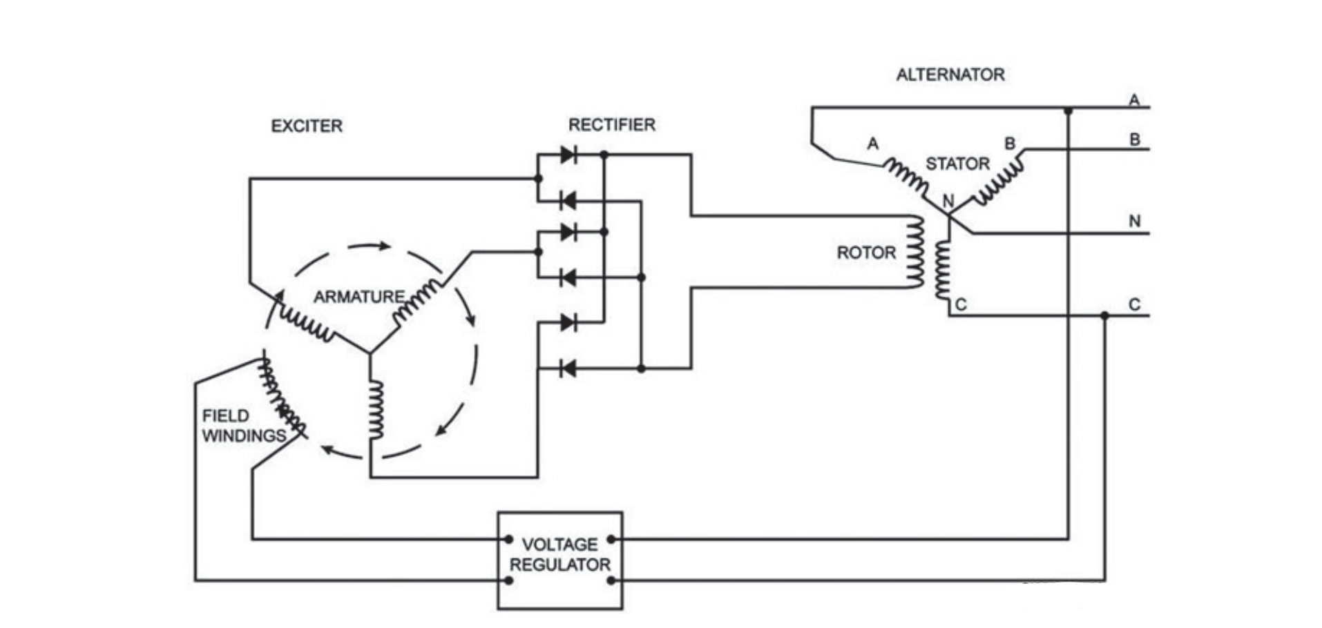
The exciter, shown in the bottom of figure, has stationary field windings that provide the magnetic field to produce electricity. The windings are coils of wire wrapped around a soft iron core. A small DC signal provides the current necessary to establish the magnetic field. The soft iron core usually holds some residual magnetism. This allows the exciter to build up a voltage output before the DC signal establishes the magnetic field.

Three-phase AC exciter
Armature
The armature, shown in the top of figure, is the rotating conductor of the exciter. The armature provides both the conductor and relative motion you need to produce voltage. Manufacturers arrange these conductors so the output is a three-phase wye configuration. This configuration provides the alternator with a smoother signal for its magnetic field.
Rectifier
The rectifier includes six diodes and a surge suppressor mounted on a fan connected to the main shaft. This is the same shaft that holds the alternator and exciter rotors. The diodes make up a three-phase bridge rectifier. These diodes connect to the output of the armature with three in forward bias and three in reverse bias, as shown in the figure below. This allows the three-phase signal to reach the alternator windings connected to the rectifier output. This takes the three-phase AC output produced by the field windings and armature and changes it into a relatively smooth DC signal. Since the rectifier is part of the exciter, we consider the exciter output to be DC.

Rotating components and circuits.
Alternators
Alternators provide power to customers to use to operate electronic equipment. This output must be stable and reliable to prevent damaging the equipment connected to it. This is especially true in today’s world of high tech electronics. This type of equipment is extremely sensitive and you must provide steady power to it. The basic components are very similar to the ones in the exciter.
Rotor assembly
The rotor assembly is a device that provides the magnetic field necessary to produce electricity. As the name implies, the rotor is the rotating portion of the alternator. It consists of a shaft, field windings, interpoles, and damping windings.
Shaft
The shaft holds all of the rotating components on the alternator. This includes the field windings and damping windings, as well as the armature and rectifier of the exciter. This shaft bolts to the engine that provides the rotation. The shaft also holds cooling vanes to circulate cooling air through the alternator assembly.
Field windings
The field windings provide the main magnetic field to produce electrical power. This magnetic field rotates as the shaft rotates to create the relative motion needed to produce electricity. These windings are coils of wire wrapped around a pole piece. The pole piece, typically made of soft iron to enhance the magnetic field, mounts to the shaft. These windings are laminated to separate the individual wires and protect them from corrosion. This also helps conduct the magnetic field when current passes through the wire.
Interpoles
Interpoles and windings offer a slight magnetic force that aligns the main magnetic field so it remains most effective. Remember, magnetic lines of force never cross each other; if you introduce a magnetic field near another magnetic field, they move to allow the new magnetic field to exist. Placing small magnetic fields at key locations keeps the main magnetic field focused in the right direction and prevents any distortion.
Damping windings
Damping windings are copper bars connected to the end of the rotor. They help the generator maintain a stable voltage under varying load conditions. The damper rings around the rotor assembly connect the damper windings of all pole pieces into one continuous damping circuit. These windings do not cut through the magnetic fields under normal conditions. If the alternator begins to change speed, the damping windings then cut through the magnetic fields. This causes them to oppose speed changes by increasing or decreasing counter torque necessary to oppose the change.
Stator assembly
The stator consists of a frame and the conductors. These conductors remain stationary. These conductors are coils of wire wrapped around a series of bars. This provides the conductor with more material to produce electricity. Manufacturers arrange the conductors in several configurations, which we will discuss in more details a little later in this unit. The stator is where the output of the alternator comes from. The frame connects to the frame of the engine and protects all of the internal components.
Voltage regulator
A small part of the alternator output current goes to the voltage regulator, which changes it to DC to send back to the exciter. The voltage regulator varies the current to the exciter field to maintain a steady alternator output voltage under varying load conditions. The voltage regulator mounts externally to the exciter sending the current to the stationary field windings. There are two basic types of voltage regulators you work with in the power production field––self-exciting and permanent magnet.
Self-exciting voltage regulators
Self-exciting voltage regulators use a soft iron core at the exciter to create the initial voltage in the alternator. This iron core stores a little bit of the magnetism produced during normal operation. We refer to this as residual magnetism. As the voltage in the alternator builds up, the regulator increases the voltage, which increases the magnetic field to the exciter, thus increasing the alternator’s output voltage. Once the voltage is at the preset level, the regulator adjusts the voltage to maintain the output of the alternator at a constant level. This is the type of regulator that you will find on many of the commercial grade generators.
Permanent magnetic voltage regulator
The permanent magnetic voltage regulator works much the same way as the self-exciting regulator. The biggest difference is that it uses a permanent magnet instead of a soft iron core. The magnetism builds up the voltage during start up. Once the regulator gets power, it increases the voltage to the coil and increases the magnetism, thus increasing the voltage output. Once the output voltage of the alternator reaches the preset level, it then controls the voltage to maintain it at a constant level. You can find this regulator on some of the newer generators on the market.
Each of these components is an equally important part of the production of AC voltage. You now know the principles to produce voltage and the components that do the job. Now lets talk about how these components work together to produce AC voltage.
Generator Alternator Operation
You know the production of AC current requires three things—a magnetic field, conductors, and relative motion. You also know how these work together to generate the AC current. You now know the components that make up an alternator. Let’s take a look at these components and determine what each part does to produce stable and controllable electrical power.
Basic operating principles
Before the generator starts, the alternator sits motionless (no output voltage from the alternator). Follow the diagram below as you read through the next few paragraphs. As the alternator begins to rotate, the power generation system starts to come to life. Most exciters use soft iron cores that retain residual magnetism. This small magnetic field extends across the conductors of the armature. As the alternator rotates, you now have relative motion to go with the magnetism and conductors. This induces a small voltage onto the armature.
This induced voltage moves to the rectified assembly changing the three-phase AC signal into DC. This DC signal then moves to the main windings on the alternator rotor. The current moving through the windings creates a magnetic field. The rotating magnetic field cuts across the stationary conductors, inducing voltage at the stator conductors. This voltage is a three-phase AC output for the alternator to provide the customer power.
Since the generator started with a small residual magnetism, the output voltage is also small. Part of the output voltage enters the voltage regulator. The voltage regulator senses the output voltage is low and provides an increased amount of current to the exciter windings. This increase in current enters the field windings creating a stronger magnetic field. The stronger magnetic field creates more voltage induced at the armature.
Alternator diagram.
The increased armature voltage changes into DC and moves into the main windings of the rotor. This increase in current causes an increased magnetic field. The increased magnetic field induces more voltage on the stator conductors to increase the output voltage of the alternator. Some of the output voltage returns to the voltage regulator to determine the voltage value.
This cycle continues until the output voltage of the alternator reaches the predetermined level. Once this happens, the voltage regulator will maintain the current supplied to the exciter field windings at steady levels to hold the voltage steady.
Alternators using permanent magnet generators for exciters
Many exciters use the output voltage of the alternator for both a reference and for supplied current for field excitation. However, some only use the alternator output for reference only and use what is a called a permanent magnet generator (PMG) for excitation current. The PMG consists of a rare earth magnet and provides a deep pool of energy. (See figure below)

Alternator with PMG diagram.
Operating principles for changes in voltage
Once the alternator reaches operating speed and operating voltage levels, the voltage regulator monitors the voltage output of the alternator to keep it steady. If the voltage level begins to drop, the voltage regulator senses the lower than normal level and increases the current to the exciter field windings. This increase in current to the winding causes the magnetic field to get stronger. This causes the amount of voltage induced at the armature to increase. The increased voltage changes to DC at the rectifier and moves on to the rotor main windings. This causes an increase in current making the magnetic field stronger. This induces more voltage at the stator conductor increasing the alternator output.
If the output voltage of the alternator gets high, the voltage regulator senses a higher than normal voltage. It then decreases the current flow to the exciter field windings. This weakens the magnetic field decreasing the induced voltage at the armature. This decrease in voltage changes to DC and moves into the rotor main windings. This causes a decrease in the current flow through the windings decreasing the strength of the magnetic field. The stator conductor has less voltage induced into it decreasing the output voltage of the alternator.
Making manual adjustments to the alternator voltage levels
The voltage regulator has an adjustment attached to it. This allows you to make small adjustments to the output voltage of the alternator. What you are really adjusting is the reference voltage; the voltage regulator compares the output voltage level. This makes the voltage regulator read the output voltage as high or low and make an adjustment to the current applied to the exciter field windings.
If the output voltage level is too high, turn the voltage adjustment down. This lowers the reference voltage making the voltage regulator read the output voltage as too high. This makes the current level applied to the exciter field windings decrease lowering the magnetic field and decreasing the voltage level induced at the armature. This lower level of voltage goes through the rectifier changing it to DC and moves on to the rotor. The decreased level of current in the main windings decreases the magnetic field to decrease the voltage induced at the stator conductor. This decreases the output voltage of the alternator.
If the voltage level is too low, adjust the voltage by turning the voltage adjustment up. This tells the voltage regulator the output voltage is too low. The voltage regulator again compares the reference and output voltages and makes adjustments to the magnetic fields opposite of what was described above to increase the voltage induced in the stator conductor. This increases the output voltage of the alternator.
In conclusion, a generator creates electricity thanks to the use of an AC alternator. The operation of an alternator is relatively easy to understand. Each component performs its job providing the self-sufficient means to produce AC voltage. All it needs is the relative motion provided by the generator’s engine.
Do they require maintenance?
This depends on the manufacturer, as with any equipment maintenance, testing and inspections are necessary to keeping alternators and exciters in top notch conditions. Maintaining your generator is an important part of ensuring it delivers the electrical power when you need it!
We at Tactical Power Generation Services, LLP are knowledgeable and more than qualified to service, maintain, and repair your power systems.